
- loading bays for tank trucks, rail tankers, IBCs, and similar
- fuel stations for automobiles
- refuelling stations for airplanes and helicopters
- recirculation systems in industrial plants
- power generation plants
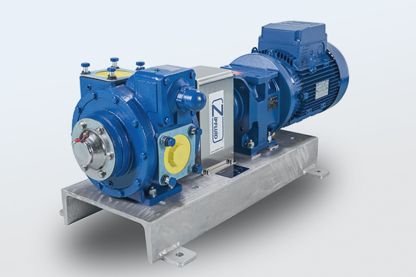
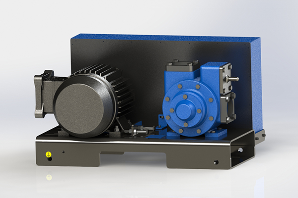
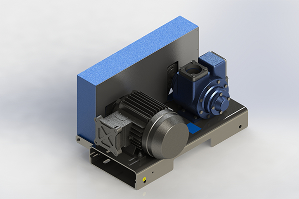
The Zipfluid pump units are generally composed of:
- a pump head (suitable for fuels and solvents)
- an engine (gasoline or diesel)
- a coupling system with reducers or belts and pulleys
- a galvanized steel base
Our Pump Groups

PG Pump Groups are assembled with PU series pumps, suitable for fuels and solvents, coupled with electric or diesel engines through gearbox or belt and pulley and housed on galvanized carbon steel bases. They can be installed on plants, marine or aviation groups, in stationary or movable assets.
• Performance data| Size | Trasmission | @ rpm | Flowrate | Required power | ||
|---|---|---|---|---|---|---|
| Lpm | M3/h | kW | Hp | |||
| 2″ | Belts – Gearbox | 520 | 220 | 13 | 1.5 | 2.0 |
| 2″ | Belts – Gearbox | 640 | 270 | 16 | 2.2 | 3.0 |
| 2 ½” | Belts – Gearbox | 520 | 370 | 22 | 3.0 | 4.0 |
| 2 ½” | Belts – Gearbox | 640 | 450 | 27 | 4.0 | 5.5 |
| 3″ | Belts – Gearbox | 520 | 800 | 48 | 5.5 | 7.5 |
| 3″ | Belts – Gearbox | 640 | 1000 | 60 | 7.5 | 10.0 |
| 4″ | Belts – Gearbox | 400 | 1530 | 92 | 11.0 | 15.0 |
| 4″ | Belts – Gearbox | 500 | 1900 | 115 | 15.0 | 20.0 |
Appropriate Flow rate (lpm) and Power (kW) are based on a 100 ssu (22 cP).
Ask to our staff for Characteristic Curves, flow rates and Power requirements at other Heads and viscosities.
- 94/9/EC Directive (ATEX)
- 2006/42/EC Directive (Machinery)
- Start / Stop button
- PD meter
- Inlet filter
- Different inlet and outlet pump connections
- Magnetothermic switch
- Trolley
- Electrical: IP 65 – ATEX II 2 G – ATEX II 3 G
- Diesel: manual or electrical start
- Belts and pulleys
- Gearbox
Volumetrics Pumps

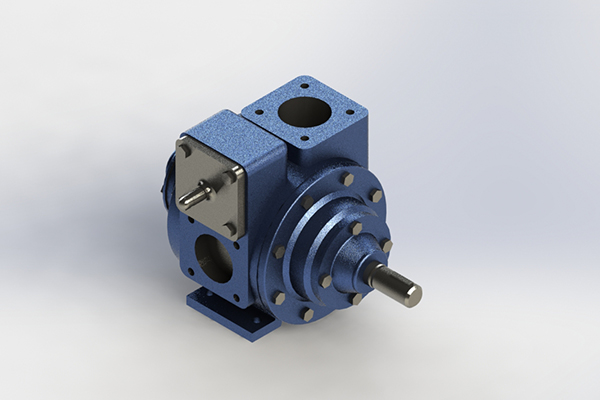
Volumetric, rotary, self-priming vane pumps PU series are suitable for fuels (PU1) and solvents (PU2). They can be installed on trucks, plants, marine or aviation groups, coupled with electrical, hydraulic or diesel motor.
• Performance data| Size | @ rpm | Flowrate | Required power | ||
|---|---|---|---|---|---|
| Lpm | M3/h | kW | Hp | ||
| 2″ | 520 | 220 | 13 | 1.5 | 2.0 |
| 2″ | 640 | 270 | 16 | 2.2 | 3.0 |
| 2½” | 520 | 370 | 22 | 3.0 | 4.0 |
| 2½” | 640 | 450 | 27 | 4.0 | 5.5 |
| 3″ | 520 | 800 | 48 | 5.5 | 7.5 |
| 3″ | 640 | 1000 | 60 | 7.5 | 10.0 |
| 4″ | 400 | 1530 | 92 | 11.0 | 15.0 |
| 4″ | 500 | 1900 | 115 | 15.0 | 20.0 |
Appropriate capacities and horsepower (hp) are based on at 100 ssu (22 cP) fluid at 50 psi (3.5 bar) delivered pressure. Ask our staff for Characteristic Curves, flow rates and Power requirements at other pressures and viscosities.
• Maximum operating limits data
| Size | @ rpm | Flow rate | Viscosity | Different Pressure (bar) | Working Pressure (bar) | ||
|---|---|---|---|---|---|---|---|
| Lpm | M3/h | ssu | cP | ||||
| 2” | 780 | 330 | 20 | 20000 | 4250 | 8.6 | 12 |
| 2½” | 780 | 600 | 36 | 20000 | 4250 | 8.6 | 12 |
| 3” | 640 | 1000 | 60 | 20000 | 4250 | 8.6 | 12 |
| 4” | 500 | 1900 | 114 | 20000 | 4250 | 8.6 | 12 |
- 94/9/EC Directive (ATEX)
- 2006/42/EC Directive (Machinery)
- Sizes: from 2” to 4”
- Self-adjusted blades
- Built-in adjustable by-pass
- Mechanical seals
- Ball bearing
- Easy maintenance
- Lay out: left or right hand
- Max operating temperature 150 °C
- Max operating viscosity 2200 cSt
- PTFE seals and rotor shaft in AISI 304 for solvents (PU2)
- Square flanges (inlet/outlet), socket weld type, in carbon steel
- Inlet filter
- Power Take-off flanged connection
- Bell housing for hydraulic motor
- Hydraulic engine


